1 Sensor Architecture Description
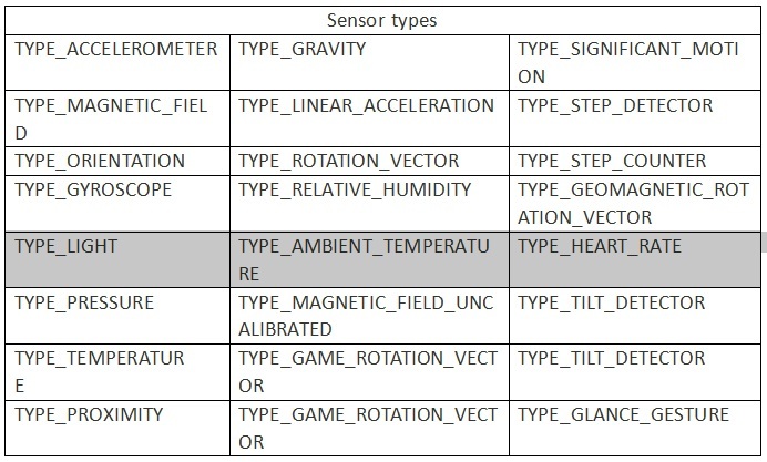
1.1Android sensor support types
Now Android support sensor types as follow
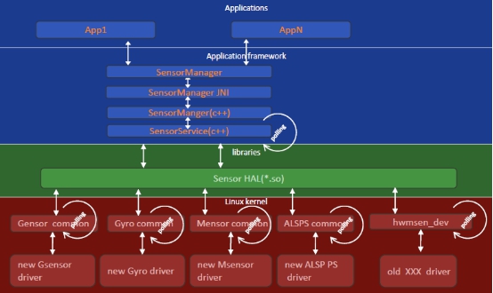
1.2 Sensor system Architecture
1.3 HAL & Driver Work Flow
1.4 Config File
android:
device\${COMPANY}\${PROJECT}\ProjectConfig.mk
kernel:
kernel-3.xx\arch\armxx\configs\$(proj)defconfig and $(proj)debug_defconfig
kernel-3.xx\arch\armxx\boot\dts\$(proj).dts
Init.rc:
alps\device\mediatek\${PLATFORM}\init.xxx.rc
2 Sensor Customization
2.1 HAL Customization
no
3 Driver Customization
3.1 Config codegen.dws
Config the codegen.dws with DCT tool:
(1)Run the drvgen.exe and open the codegen.dws file
• Drvgen.exe path:
– alps\kernel-3.18\tools\dct\DrvGen.exe
• amt6797_64_open.dws path:
alps\kernel-3.18\drivers\misc\mediatek\dws\$(platform)\$(proj)\amt6797_64_open.dws
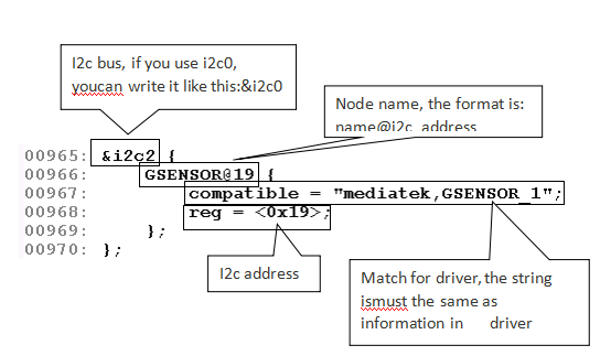
(2)config i2c bus and address
(3)exit and save the amt6797_64_open.dws
(4) Change the name to codegen.dws and copy to the follow path:
lk:
alps\vendor\mediatek\proprietary\bootable\bootloader\lk\target\$(proj)\dct\dct\codegen.dws
(5)If the sensor have used EINT like alsps, it must config gpio and eint.
if the sensor do not use EINT, please ignore this step.
(6)exit and save the codegen.dws
(7) Change the name to codegen.dws and copy to the follow path:
gen.dws
lk:
alps\vendor\mediatek\proprietary\bootable\bootloader\lk\target\$(proj)\dct\dct\codegen.dws
3.2 Driver Customization-parameters
3.2.1 ACCELEROMETER PARAMETERS CUSTOMIZATION
Note:
If the project is 32bits, armxx is arm.
If the project is 64bits, armxx is arm64.
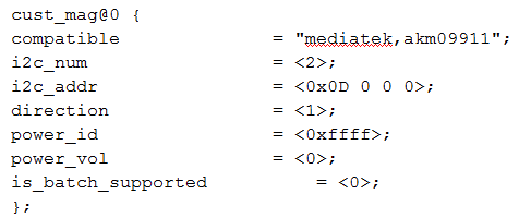
b、Accelerometer parameters description:
compatible :Identification for driver
i2c_num :i2c channel ,depend on hardware
direction :Sensor layout direction
power_id :LDO id which the sensor has used
power_vol :LDO voltage which the sensor hse used
is_batch_supported :support batch mode or not
3.2.2 NOTICE
Mapping coordinate(accelerometer, gyroscope, magnetometer)
3.2.3 GYROSCOPE PARAMETERS CUSTOMIZATION
a、Config the parameters in the path:
alps\kernel-3.18\arch\armxx\boot\dts\$(proj).dts
Note:
If the project is 32bits, armxx is arm.
If the project is 64bits, armxx is arm64.
b、Gyroscope parameter description:
compatible :Identification for driver
i2c_num :i2c channel ,depend on hardware
direction :Mapping the coordinate
power_id : LDO id which the sensor has used
power_vol : LDO voltage which the sensor hse used
firlen Data :filter length, usually, it is set with 0
is_batch_supported :gyro support batch mode or not
3.2.4 MAGNETOMETER PARAMETERS CUSTOMIZATION
a、alps\kernel-3.18\arch\armxx\boot\dts\$(proj).dts
Note:
If the project is 32bits, armxx is arm.
If the project is 64bits, armxx is arm64.
b、Magnetometer parameter description:
compatible :Identification for driver
i2c_num :i2c channel ,depend on hardware
Direction : Sensor layout direction
power_id : LDO id which the sensor has used
power_vol : LDO voltage which the sensor hse used
is_batch_supported :support batch mode or not
3.2.5 ALSPS PARAMETER DESCRIPTION
a、Config the parameters with Device Tree
The customization file is :
alps\kernel-3.18\arch\armxx\boot\dts\$(project).dts
Note:
• If the project is 32bits, armxx is arm.
• If the project is 64bits, armxx is arm64.
b、Alsps parameter description
Compatible : Identification for driver
i2c_num :i2c channel ,depend on hardware
polling_mode_ps 0 :interrupt mode,1:polling mode
polling_mode_als 0 :interrupt mode,1:polling mode
power_id : LDO id which the sensor has used
power_vol : LDO voltage which the sensor hse used
als_level : The als data mapping table:
als_value : als_level-->als_value
ps_threshold_high : ps_data > ps_threshold_high : close
ps_threshold_low : ps_data < ps_threshold_low : far away
is_batch_supported_ps : ps support batch mode or not
is_batch_supported_als :als support batch mode or not
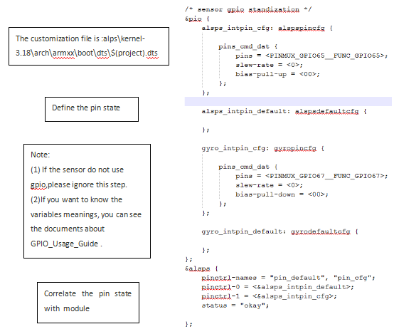
3.2.6 DRIVER CUSTOMIZATION-GPIO
Config the pin function with Device Tree
4 Choose sensor P/N
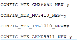
Choose the special sensor P/N in kernel defconfig file:
arch/armxx/configs/$(proj)debug_defconfig
arch/armxx/configs/$(proj)defconfig
Example:
And suggest use “make menuconfig” to do it
5 Sensor Compatible
5.1 Detection principle
– Using i2c connection and device information to detect the different
device.
– If using one i2c address to connect device fail, then don’t choose this
device.
– When i2c connection is success, then read the device information. If the
information is right, then choose this device. Otherwise, don’t choose it.
5.2 There use accelerometer as example
Step 1:
– The first sensor driver do not need change.
– It still use DCT to configure the first sensor’s i2c address.
Step 2:
– Modify the second sensor driver.
Step 3:
– Configure the second sensor’s i2c address in $(project).dts
tep 4:
– Configure the customization parameter for second sensor in $(project).dts
cust_accel@0 {
compatible = "mediatek,icm20645g";
i2c_num = <1>;
i2c_addr = <0x68 0 0 0>;
direction = <3>;
power_id = <0xffff>;
power_vol = <0>;
firlen = <0>;
is_batch_supported = <0>;
};
cust_alsps@0 {
	compatible				= "mediatek,cm36558";
	i2c_num					= <1>;
	i2c_addr				= <0x51 0 0 0>;
	polling_mode_ps			= <0>;
	polling_mode_als		= <1>;
	power_id				= <0xffff>;
	power_vol				= <0>;
	als_level = <0 328 861 1377 3125 7721 7767 12621 23062 28430 33274 47116 57694 57694 65535>;
	als_value = <0 133 304 502 1004 2005 3058 5005 8008 10010 12000 16000 20000 20000 20000 20000>;
	ps_threshold_high		= <26>;
	ps_threshold_low		= <21>;
	is_batch_supported_ps	= <0>;
	is_batch_supported_als	= <0>;
};
Working
